
ProcessOpt tutorial: Flotation Cell Model
Configure a flotation cell with level, air and entrainment - step by step in ProcessOpt
1 Fundamental
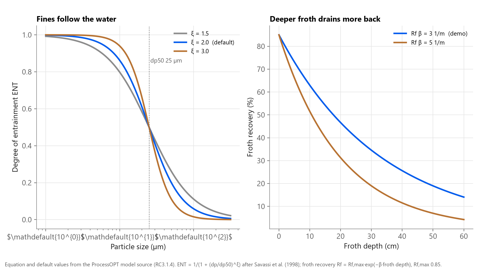
Particles reach the concentrate by attaching to bubbles or by riding with the water.
True flotation through the froth, plus entrainment with water
Collection-zone kinetics k scale with Jg; the froth recovers a fraction Rf that falls with froth depth; gangue reports by entrainment in proportion to water recovery and ENT(dp).
2 Objective
A cell model with real level, air and valve behaviour, ready to chain into a bank.
By the end you will have
- A dynamic cell whose pulp level follows the tail valve
- Recovery that responds to air, froth depth and reagents
- Concentrate grade affected by entrainment of fines
- A building block for rougher, scavenger and cleaner banks
3 Step by step
Every screen below is a real ProcessOpt screenshot.
Step 1 - Add a Simulation node and wire it into the scan
Every model in ProcessOpt runs inside a Simulation node. The node is executed once per scan cycle in the order of the graph, so place it after the logic that writes its inputs and before the logic that reads its outputs.
- Project Configuration > Logic Editor
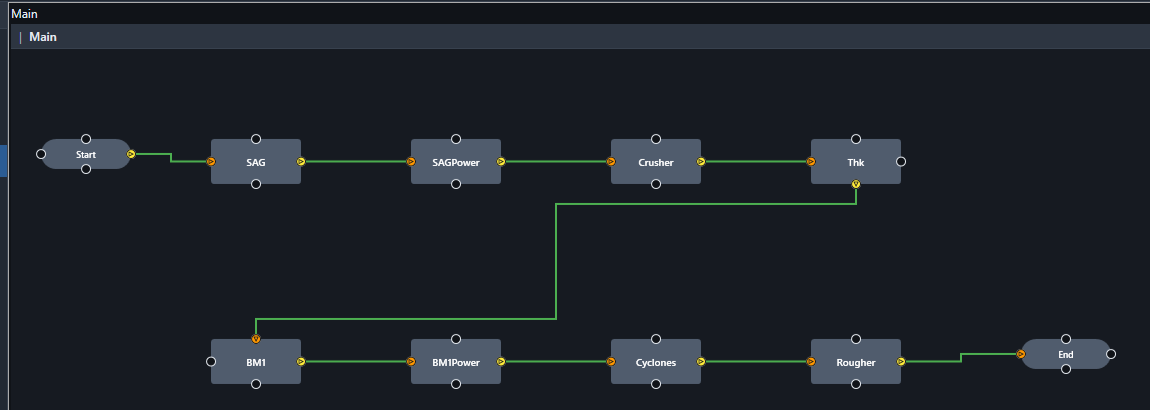
- Right-click the canvas > add a Simulation node, name it Rougher
- Connect Start > Rougher > End so it runs every scan cycle (1 s here)
- One node per unit: the demo project has eight models on one canvas
Step 2 - Choose the model type and name the I/O tags
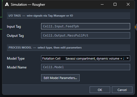
- Double-click the node to open the Simulation dialog
- Model Type: Flotation Cell (Savassi compartment, dynamic volume, Jg, level control)
- Input Tag and Output Tag are the two headline signals; every other result gets its own tag automatically
- Press Edit Model Parameters... for the full model sheet
Step 3 - Cell geometry and kinetics
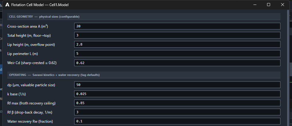
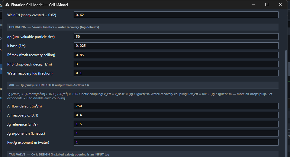
- Area 20 m², height 3 m, lip at 2.8 m, lip perimeter 5 m, weir Cd 0.62
- Valuable particle size 50 µm, k base 0.025 1/s
- Froth recovery ceiling 0.85, drop-back decay β 3 1/m
- Water recovery Rw 0.10
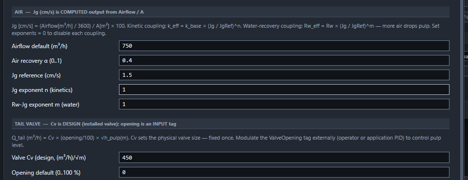
Step 4 - Air and the tail valve
- Airflow 750 m³/h → Jg computed from airflow / area
- Kinetics and water recovery scale with (Jg / Jg ref)^n
- Tail valve Cv 450 is the installed valve; opening is a live input
- Wire the opening to a level PID for realistic level control
Step 5 - Feed, entrainment and start-up
- Feed water and feed grade (%): wire from the upstream tail grade in a bank
- Entrainment dp50 25 µm, ξ 2 (Savassi 1998)
- Reagent doses and initial pulp volume further down the sheet
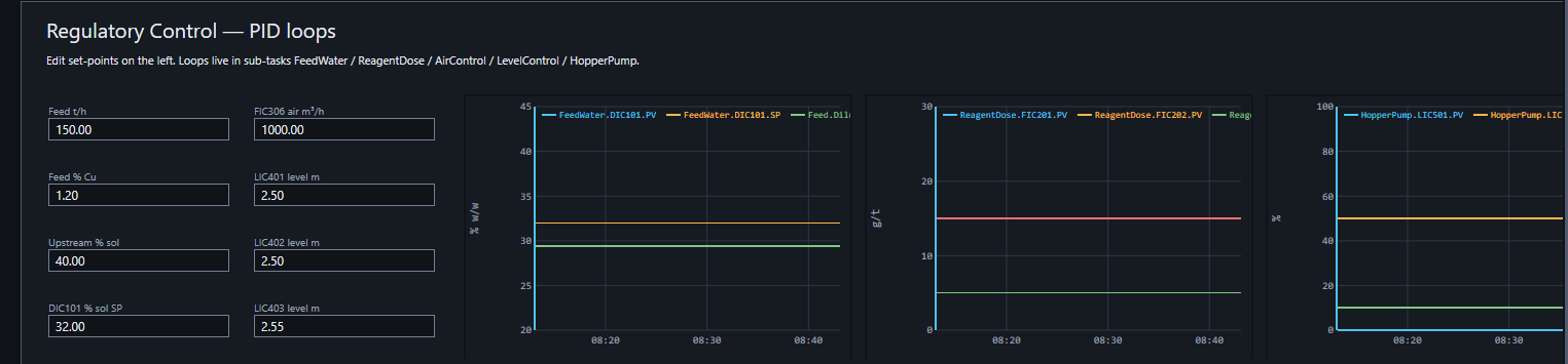
Step 6 - Run it: tail valves on level PIDs, air on flow loops
Flotation demo project, 5 minutes after a cold start: cells are still filling (first cell level 1.56 m against a 2.5 m set-point) and recovery is only starting to build as the froth forms. Allow the bank to fill before judging recovery and grade; on the plant the same model starts from the initial pulp volume you enter in Step 5.
Checks before you trust the model
- Level settles when the valve opening is constant
- More air raises recovery up to a point and raises water recovery
- A deeper froth lowers recovery and improves grade
- Fine gangue in concentrate follows water recovery
Request a demo.
Talk to an engineerSources
- ProcessOpt RC3.1.4 - process model source code and editor dialogs, Aeterna Automation, 2026
- An empirical model for entrainment in industrial flotation plants, Savassi, Alexander, Franzidis and Manlapig, Minerals Engineering 11(3), 1998
- The modelling of froth zone recovery in batch and continuously operated laboratory flotation cells, Vera, Mathe, Franzidis, Harris, Manlapig and O'Connor, Int. J. Mineral Processing 64, 2002
- Wills' Mineral Processing Technology, 8th edition, Wills and Finch, Butterworth-Heinemann, 2016